Autor: Pirat
7.5. Preparation to export
Once the whole UV is ready, we can proceed to moving mirrored element by 1 quarter right. Thanks to that everybody who happen to work on the object will instantly notice which parts are not unique. It is good to label mirrored fragment on earlier stages, for example by material ID. Later on, it will be easier to determine which UV islands should be moved.

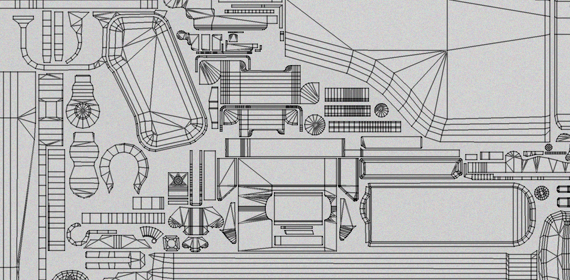
7.4. Layout
From the technical point of view is doesn’t matter how we will lay out islands on the UV. However, there are a few tips how to do that. The most important is to create such mesh which allows everybody to see where a particular element is. The way of cutting and moving faces next to each other is also important.

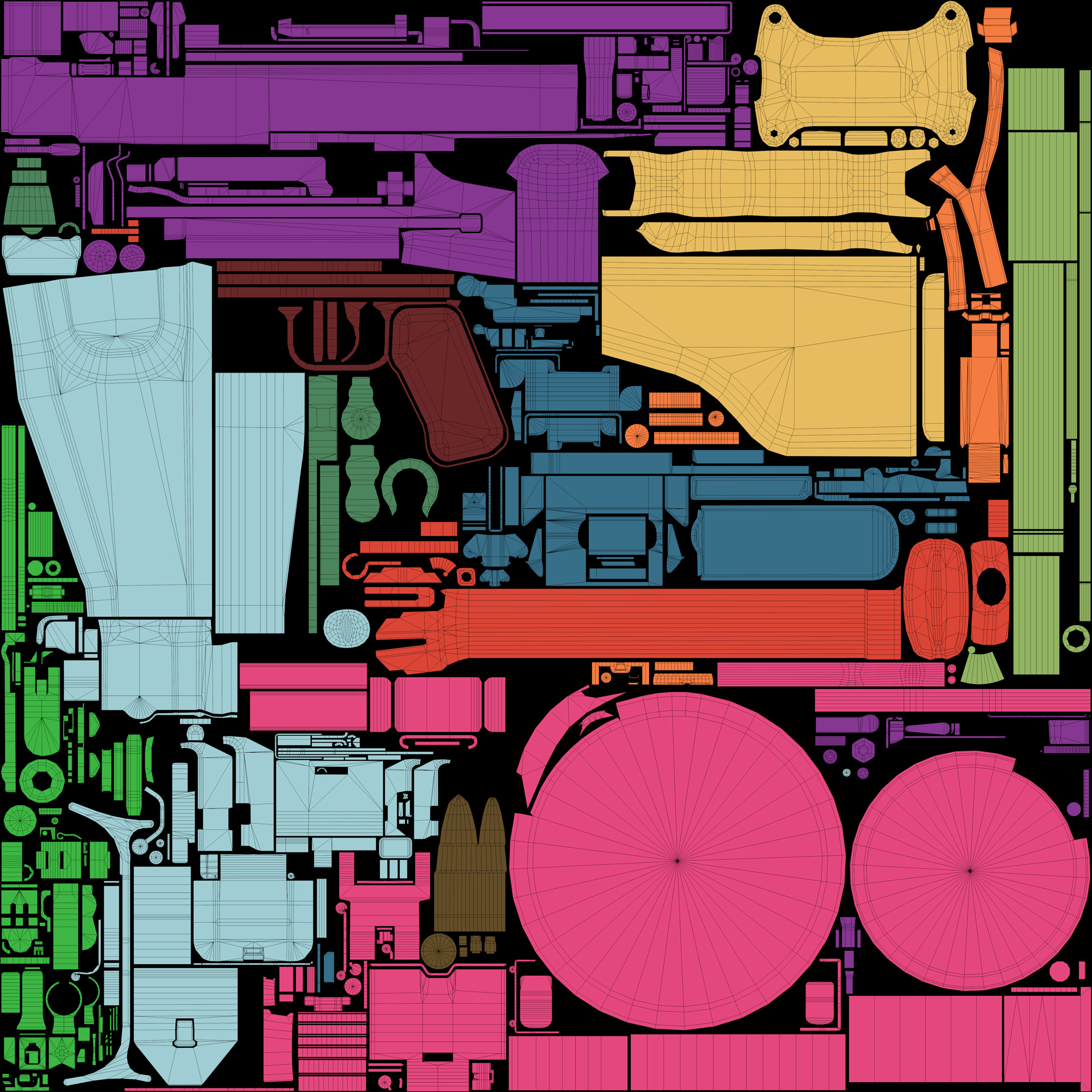
Each element should be placed next to another, laid out in a logical way (for example: bullets next to a magazine, trigger next to a slide, etc.). It makes texturing much easier. A graphic does not have to search for elements on the whole mesh, he knows they are nearby.
Laying up the UV mesh according to the rules of gravity, using software to generate textures will spare a lot of problems connected with the angle of leaking / patterns. It will also facilitate placing typography. Use gravity checker to run viewport.

Another important parameter in laying up mesh is the distance between islands. You should adopt a rule saying that the space should be of minimum 4-6 px for the targeted seize of texture (when we bake an object in higher <not target> resolution, the space should be increased by the same multiplier).
The wider the spaces, the more substantial loos in the texture resolution. Keeping spaces is, however, necessary due to edge padding. This problem was described in more details on polycount wiki.
Noise pattern is used to measure spaces.
7.3. Smaller elements
A small trick that makes player think that weapon has high resolution with a texture is to improve the UV size of small details, such as e.g. screws. Small details are eye-catching, especially when they break monotonously a homogenous plane. source
Laymen treat the details resolution as an indicator of quality. That’s why it is worth to spare some space on UV for it.
![Textures.com. Lights0033 [online] source: http://www.textures.com/download/lights0033/46675](http://piratportfolio.com/fpp_eng/wp-content/uploads/2015/11/7.3.jpg)
![Textures.com. Lights0033 [online] source: http://www.textures.com/download/lights0033/46675](http://piratportfolio.com/fpp_eng/wp-content/uploads/2015/11/7.3.A_II.jpg)
This additional multiplier (base × hierarchy × additional multiplier) should not exceed about 1.15 and is usually reasoned by the amount of free space on the UV layout.
Christopher G. Healey, Perception in Visualization [online]. Department of Computer Science, North Carolina State University.
2014. Preattentive Processing source: http://www.csc.ncsu.edu/faculty/healey/PP/index.html
2014. Preattentive Processing source: http://www.csc.ncsu.edu/faculty/healey/PP/index.html
7.2. The order of hierarchy
On the basis of the order of hierarchy that has been set in the low poly object, UV islands need to be adequately scaled so to „meet the needs” of resolution. The closer to the camera, the higher the UV scale.
After cutting and laying down islands, so that the UV aspect ratio was proportional (the same for the whole object), it’s time for scaling. The scale’s multipliers usually look like that:
- 1.2 – elements placed the closest to player (scopes, optics, rear part of weapon) directly at the camera;
- 1.1 – the rest of elements placed close to the camera;
- 1.0 – the body of a weapon, magazines;
- 0.8 – barrel, the front part of a weapon
- 0.6 – elements beyond the camera

A method that allows us to make sure that all parts have a proper scale is to check it on UV chequer in the frame. If elements have similar resolution, depending on the perspective (the further, the smaller the UV island), we should get a good result.

Additionally you can improve texture with a detail map. Thanks to that we can „level” the texture in the whole weapon. However, you should remember to make an additional UV set on which all UV islands will have the same aspect ratio.
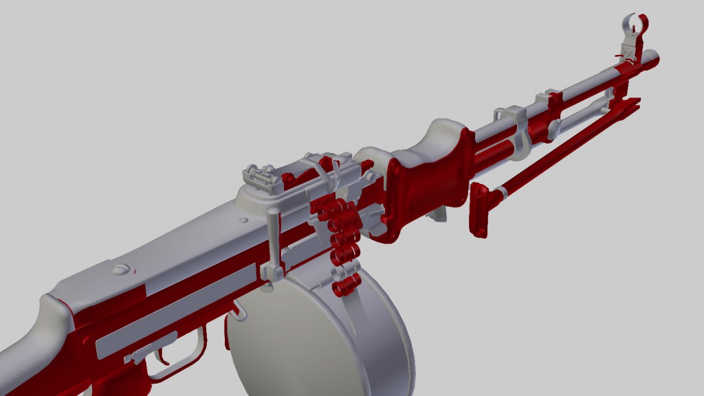
7.1. Mirror
To save some space in the UV you should mirror as much as possible. However, mirrored UV should be avoided in FPP projection (it concerns mainly such elements as scopes, triggers and upper part of a weapon).

It’s best to mirror the whole right side, which is not visible in the camera.

7.0. Textures ‒ pipeline
Depending on imposed pipeline there are a lot of ways to approach the issue of texturing. The following can be used:
- dedicated textures,
- mixed material, according to mask or color blending,
- generic textures set by material ID,
- base materials and decals,
- generating color (cartoon) only in the material instance
And many other methods…
The adjusted texturing method largely determines the way UV map will be created.
Placing the UV map will be discussed on the example of traditional texturing, as weapon is important due to the fact that it often has its own textures. Such approach is also the most extended, therefore, suits the presentation best. Experience gained in such a way will bear its fruits and will facilitate making decisions at other production processes (usually less complicated).
The work should be commenced with cutting weapon into islands with the same aspect ratio. All islands seams should be invisible in the frame.
UV mapping
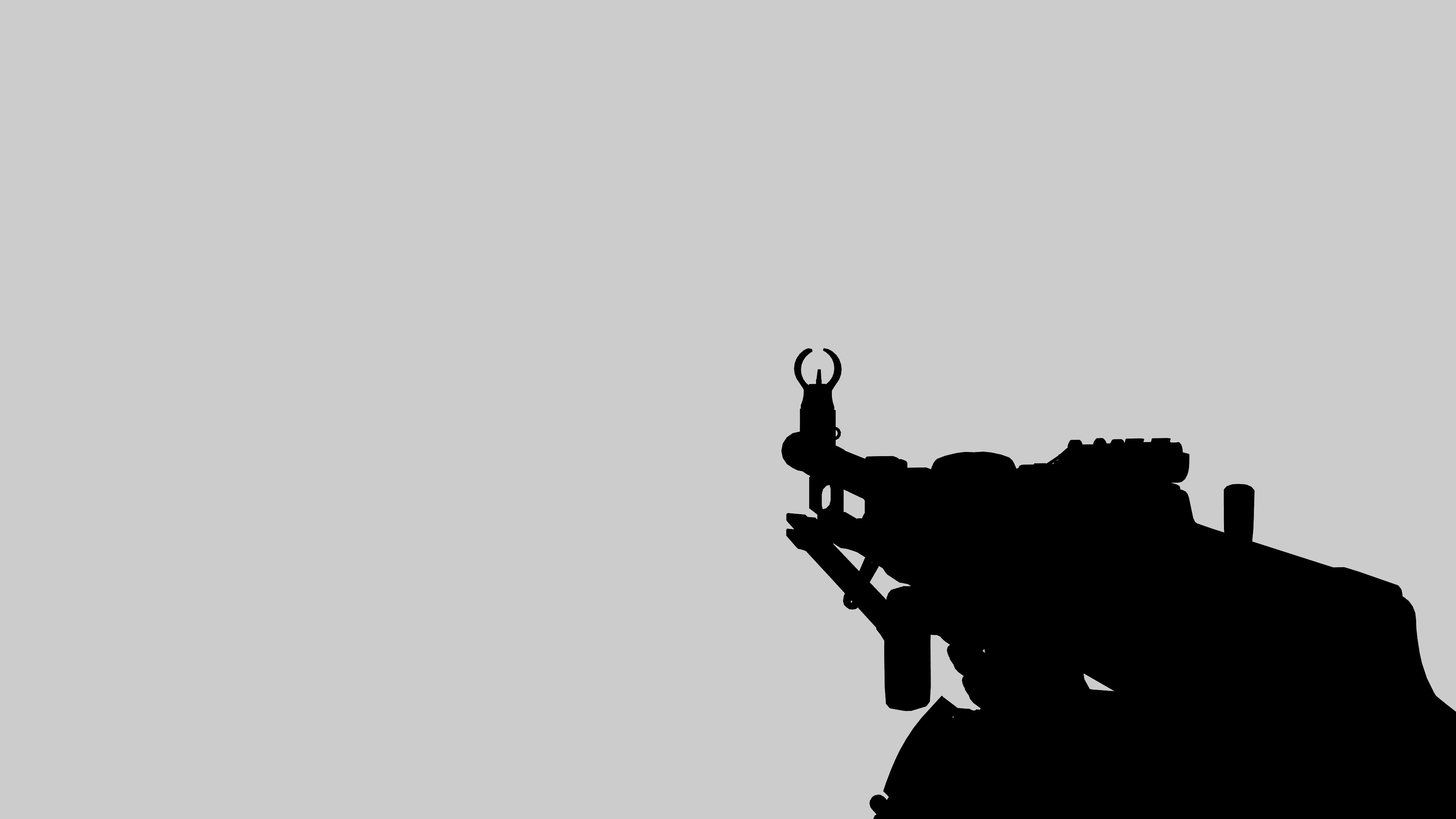
6.3. Silhouette viewport
![Valve Corporation. <b>Team Fortress 2</b> [PC]. Valve Corporation, 2007, <i>source: http://www.neogaf.com/forum/showpost.php?p=47497145&postcount=267</i>](http://piratportfolio.com/fpp_eng/wp-content/uploads/2015/11/6.5.A_IV.jpg)
6.2. Reduction of the number of tris
When we exceed the given limit but do not want to resign from the level of bevel, we should consider remodeling some parts of the high poly. Such changes should result in creation of less complicated low poly object. One of the easiest way to safe tris is to distance elements and then remove tangent faces.

After finishing the high poly object, graphic does not have to stick to it. Some changes, corrections and improvements, can still be made. Some element should be changed or erased if a situation requires it or if it is favorable for the whole object.
All faces inside an object should be removed. Redundant, invisible tris corrupt both the geometry and the UV map.